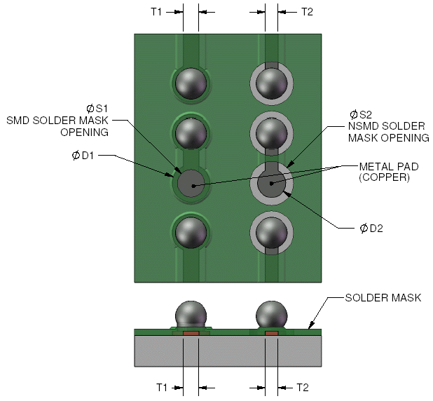
Solder Mask Defined Land Pattern Land patterns become a part of the printed board circuitry and they are subject to the producibility levels and tolerances associated with fabrication and assembly processes The producibility aspects also pertain to the use of solder mask and the registration required between the solder mask and the conductor patterns
The IPC 7351 standard specifies some important dimensions for creating a PCB land pattern for a SOIC footprint these are the pad width X pad spacing G and end to end pad dimension Z The image below shows where these three quantities fit into a component footprint Alternatively the land pattern for the exposed pad can be segmented into a symmetric array of square or rectangular lands as shown in Figure 5 This design also applies to packages with multiple exposed pads The land array can be created either by segmentation of a full copper area by solder mask openings or by
Solder Mask Defined Land Pattern
Solder Mask Defined Land Pattern
https://www.topline.tv/drawings/images/SMD_vrs_NSMD_Pads/5040001_p1a.GIF

Bl hen Bisher Sehr Sch n Paste Mask Trag die berlegenheit Feat
https://kicad-info.s3.dualstack.us-west-2.amazonaws.com/original/3X/3/4/3499cd396df84f5367fde2abc75e90a68a488e56.jpeg
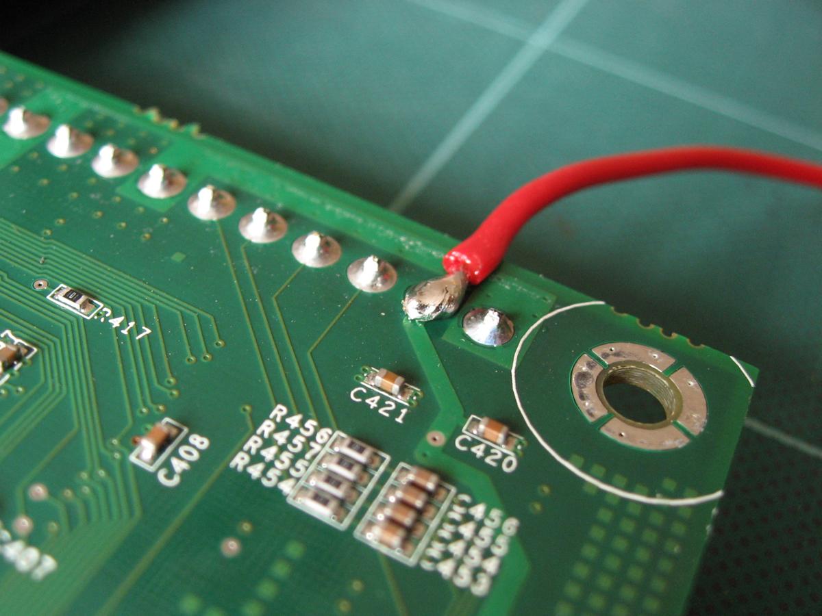
Engineering Solder Mask HandWiki
https://handwiki.org/wiki/images/2/2a/Solderedjoint.jpg
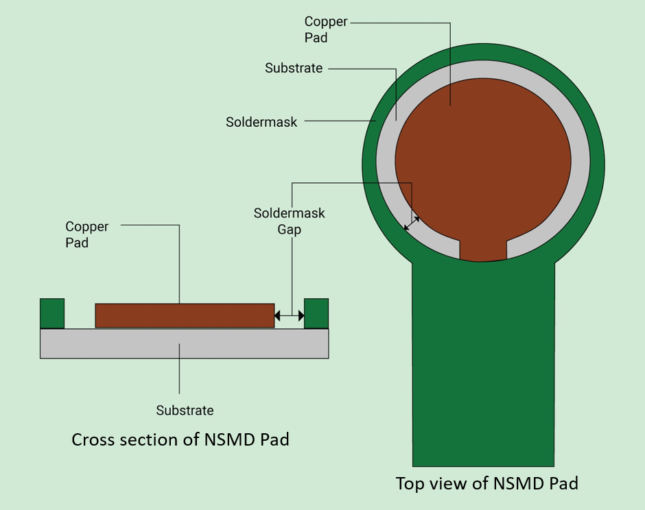
Users have the option to either use solder mask defined SMD pads or non solder mask defined NSMD pads High temperature FR 4 or BT laminate glass transition temperature Tg 170 C to 185 C is generally 2 1 Land pattern design It is recommended to use a non solder mask defined NSMD pads see Figure 9 with opening slightly larger than the land geometry as copper etching has better dimensional control than solder masking process because it allow solder to adhere to the sides of the Cu land for better reliability Figure 9
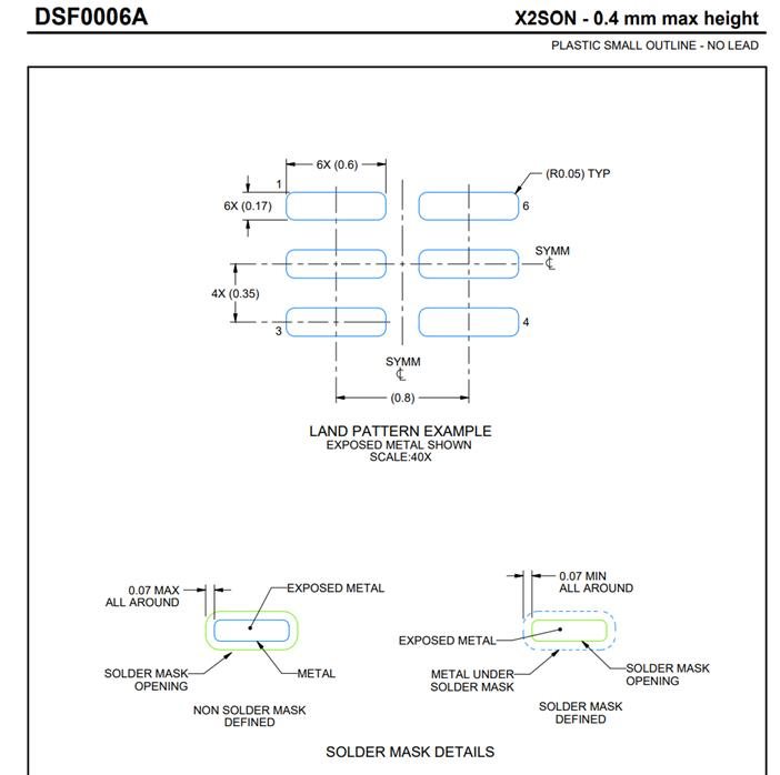
Solder Mask Design Two types of land patterns are used for surface mount packages Solder Mask Defined SMD Solder mask openings smaller than metal pads Non Solder Mask Defined NSMD Solder mask 3 1 1 Solder Mask Defined SMD land pad 5 3 1 2 Non Solder Mask Defined NSMD land pad 5 3 2 Recommended BGA footprint 6 4 Recommended fan out trace space guidelines 8
More picture related to Solder Mask Defined Land Pattern
PCB Beplay ios
https://lh3.googleusercontent.com/NbMOCwYTUtbBxp0fYCE31IOHDhWr1h3fEUtGTIIVAmgjRb-R8CTbhD_UyvMUgfehRKKoFPUOQc-R-qhI4KvlRUPCInCDxadKw-zz5KtkigpeXledeqIR6xhYkSuOZ5_Q56AbbzJ8
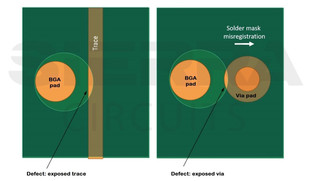
6 Common Solder Mask Errors In PCBs Sierra Circuits
https://www.protoexpress.com/wp-content/uploads/2023/07/solder-mask-misregistration-1024x600.jpg
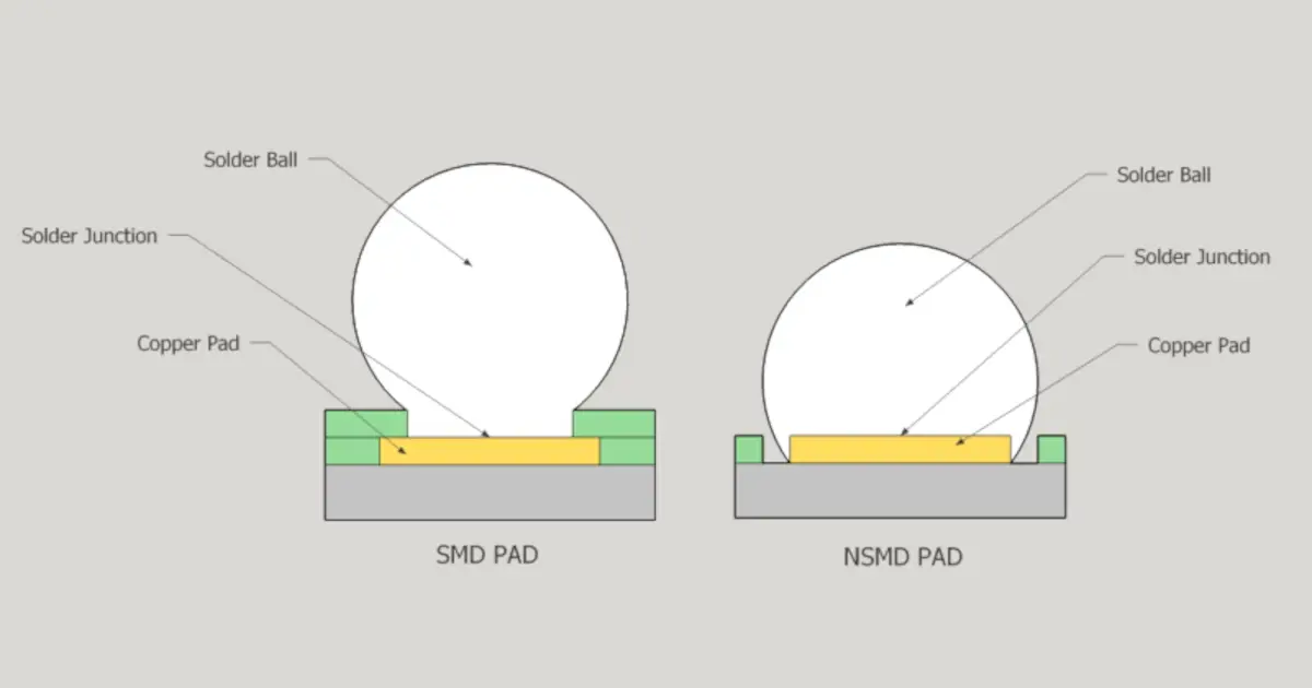
SMD Vs NSMD Best Practices For BGA Pad Creation MacroFab
https://macrofab.com/assets/uploads/og/bga-pad-creation-smd-nsmd.webp
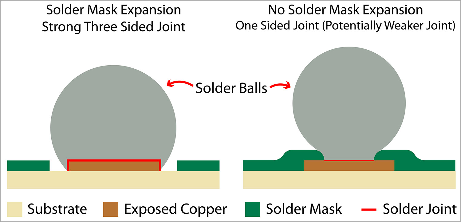
A solder mask defined SMD pad design features a solder mask layer partially laying on the edge of the PCB pad see Figure 1 The solder mask opening is slightly smaller than the pad size which creates an overlay area between the solder mask layer and the pad layer SMD pad design offers several benefits The solder lands on the package side are always Solder Mask Defined SMD The land pattern on the PCB should be designed to correspond with the land pattern on the package The land on the PCB should be Non Solder Mask Defined NSMD in order to realize the best board level reliability performance
Two types of land patterns are used for surface mount devices Solder Mask Defined SMD pads have solder mask openings that are smaller than metal pads Non Solder Mask Defined NSMD pads have solder mask opening that are larger than the metal pads The solder balls of all FBGA packages assure good solderability even after a long storage time The land pattern design and SMT mounting of FBGA type packages are based on the IPC 7351 and IPC 7095 standards A Non Sol der Mask Defined NSMD pad design is recom mended for all board pads as shown in
What Is A Solder Mask SnapMagic Blog
https://blog.snapeda.com/wp-content/uploads/Solder-Mask.png

PDF Analysis Of Solder Mask Roughness And Stencil Shape Influence On
https://i1.rgstatic.net/publication/368993337_Analysis_of_solder_mask_roughness_and_stencil_shape_influence_on_void_formation_in_solder_joints/links/64126035315dfb4cce80f4c6/largepreview.png

https://www.ipc.org/TOC/IPC-7352-TOC.pdf
Land patterns become a part of the printed board circuitry and they are subject to the producibility levels and tolerances associated with fabrication and assembly processes The producibility aspects also pertain to the use of solder mask and the registration required between the solder mask and the conductor patterns

https://resources.altium.com/p/pcb-land-pattern...
The IPC 7351 standard specifies some important dimensions for creating a PCB land pattern for a SOIC footprint these are the pad width X pad spacing G and end to end pad dimension Z The image below shows where these three quantities fit into a component footprint
Solder Mask Expansion An Essential Consideration In PCB Design And

What Is A Solder Mask SnapMagic Blog
DP83848K Land Patterns And Solder Paste Examples Interface Forum

PDF THE EFFECT OF SOLDER MASK AND SURFACE MOUNT ADHESIVE TYPES
Poskok Nastaven Zneu v n Solder Mask Defined Pads Macrosformeals

Designing With BGAs For Manufacturability And Cost Eurocircuits

Designing With BGAs For Manufacturability And Cost Eurocircuits

What Is A Solder Mask SnapMagic Blog
SN74LVC1G04 Land Pattern Logic Forum Logic TI E2E Support Forums

PDF TN009 PCB Design Guidelines For 3x3 LGA Sensors The PCB Should
Solder Mask Defined Land Pattern - 3 1 1 Solder Mask Defined SMD land pad 5 3 1 2 Non Solder Mask Defined NSMD land pad 5 3 2 Recommended BGA footprint 6 4 Recommended fan out trace space guidelines 8
